What is the magnetic force?
The magnetic force is a consequence of the electromagnetic force, one of the four fundamental forces of nature, and is caused by the motion of charges. Two objects containing charge with the same direction of motion have a magnetic attraction force between them. Similarly, objects with charge moving in opposite directions have a repulsive force between them.
In our article on magnetic fields we learned how moving charge surrounds itself with a magnetic field. In this context the magnetic force is a force that arises due to interacting magnetic fields.
How to find the magnetic force?
Consider two objects. The magnitude of the magnetic force between them depends on how much charge is in how much motion in each of the two objects and how far apart they are. The direction of the force depends on the relative directions of motion of the charge in each case.
The usual way to go about finding the magnetic force is framed in terms of a fixed amount of charge q moving at constant velocity v in a uniform magnetic field B. If we don't know the magnitude of the magnetic field directly then we can still use this method because it is often possible to calculate the magnetic field based on the distance to a known current.
The magnetic force is described by the Lorentz Force law:
In this form it is written using the vector cross product. We can write the magnitude of the magnetic force by expanding the cross product. Written in terms of the angle theta (is less than, 180, degrees) between the velocity vector and the magnetic field vector:
The direction of the force can be found using the right-hand-slap rule. This rule describes the direction of the force as the direction of a 'slap' of an open hand. As with the right-hand-grip rule, the fingers point in the direction of the magnetic field. The thumb points in the direction that positive charge is moving. If the moving charge is negative (for example, electrons) then you need to reverse the direction of your thumb because the force will be in the opposite direction. Alternatively, you can use your left hand for moving negative charge.

Figure 1: Using the right-hand-slap rule for the force due to a positive charge moving in a magnetic field.
Sometimes we want to find the force on a wire carrying a current I in a magnetic field. This can be done by rearranging our previous expression. If we recall that velocity is a distance / time then if a wire has length L we can write
and since current is the amount of charge flowing per second,
and therefore
Force on a wire
Exercise 1a:
Figure 2: Magnetic force on a wire.

Figure 2 shows a wire running through the north and south poles of a horseshoe magnet. A battery is connected to the wire which causes a current of 5, space, A to flow through the wire in the direction shown. If the magnetic field between the poles is known to be 0, point, 2, space, T, what is the magnitude and direction of the force on the 10, space, m, m section of wire between the poles?
Exercise 1b:
Suppose the magnet was shifted a little to the left so that the wire is now closer to the south pole of the magnet. Would you expect any change in the force on the wire?
Exercise 1c:
Suppose the strength of the magnet was not known. Can you suggest a way to modify this experiment to measure the strength of the magnetic field? Assume you have a ruler, string and some calibrated weights available.
Magnetic deflection of electrons in a cathode-ray tube
A cathode ray tube is an evacuated tube with an electron gun at one end and a phosphorescent screen at the other end. Electrons are ejected from the electron gun at high speed and impact the screen where a spot of light is produced on impact with the phosphor.
Because electrons have charge it is possible to deflect them in-flight with either the electric or magnetic force. Controlling the deflection allows the spot of light to be moved around the screen. Old style 'tube' televisions use this principle with magnetic deflection to form images by rapidly scanning the spot.
Exercise 2a:
Figure 3 shows a cathode ray tube experiment. A pair of coils are placed outside a cathode ray tube and produce a uniform magnetic field across the tube (not shown). In response to the field, the electrons are deflected and follow a path which is a segment of a circle as shown in the figure. What is the direction of the magnetic field?
Figure 3: Cathode ray tube experiment.

Exercise 2b:
If the electrons are known to be ejected from the electron gun horizontally at a speed v of 2, dot, 10, start superscript, 7, end superscript, space, m, slash, s, what is the strength of the magnetic field? Assume that the radius of the circular path can be approximated by L, squared, slash, 2, d where L is the length of the tube and d is the horizontal deflection.
What is a magnetic field?
A magnetic field is a picture that we use as a tool to describe how the magnetic force is distributed in the space around and within something magnetic.
Most of us have some familiarity with everyday magnetic objects and recognize that there can be forces between them. We understand that magnets have two poles and that depending on the orientation of two magnets there can be attraction (opposite poles) or repulsion (similar poles). We recognize that there is some region extending around a magnet where this happens. The magnetic field describes this region.
There are two different ways that a magnetic field is typically illustrated:
- The magnetic field is described mathematically as a vector field. This vector field can be plotted directly as a set of many vectors drawn on a grid. Each vector points in the direction that a compass would point and has length dependent on the strength of the magnetic force. Arranging many small compasses in a grid pattern and placing the grid in a magnetic field illustrates this technique. The only difference here is that a compass doesn't indicate the strength of a field.Figure 1: Vector field plot for a bar magnet.
- An alternative way to represent the information contained within a vector field is with the use of field lines. Here we dispense with the grid pattern and connect the vectors with smooth lines. We can draw as many lines as we want.The field-line description has some useful properties:Figure 2: Field line plot for a bar magnet
- Magnetic field lines never cross.
- Magnetic field lines naturally bunch together in regions where the magnetic field is the strongest. This means that the density of field lines indicates the strength of the field.
- Magnetic field lines don't start or stop anywhere, they always make closed loops and will continue inside a magnetic material (though sometimes they are not drawn this way).
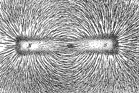
- We require a way to indicate the direction of the field. This is usually done by drawing arrowheads along the lines. Sometimes arrowheads are not drawn and the direction must be indicated in some other way. For historical reasons the convention is to label one region 'north' and another 'south' and draw field lines only from these 'poles'. The field is assumed to follow the lines from north to south. 'N' and 'S' labels are usually placed on the ends of a magnetic field source, although strictly this is arbitrary and there is nothing special about these locations.
- Field lines can be visualized quite easily in the real world. This is commonly done with iron filings dropped on a surface near something magnetic. Each filing behaves like a tiny magnet with a north and south pole. The filings naturally separate from each other because similar poles repel each other. The result is a pattern that resembles field lines. While the general pattern will always be the same, the exact position and density of lines of filings depends on how the filings happened to fall, their size and magnetic properties.Figure 3: Magnetic field lines around a bar magnet visualized using iron filings.


How do we measure magnetic fields?
Because a magnetic field is a vector quantity, there are two aspects we need to measure to describe it; the strength and direction.
The direction is easy to measure. We can use a magnetic compass which lines up with the field. Magnetic compasses have been used for navigation (using the Earth's magnetic field) since the 11ᵗʰ century.
Interestingly, measuring the strength is considerably more difficult. Practical magnetometers only came available in the 19ᵗʰ century. Most of these magnetometers work by exploiting the force an electron feels as it moves through a magnetic field.
Very accurate measurement of small magnetic fields has only been practical since the discovery in 1988 of giant magnetoresistance in specially layered materials. This discovery in fundamental physics was quickly applied to the magnetic hard-disk technology used for storing data in computers. This lead to a thousand-fold increase in data storage capacity in just a few years immediately following the implementation of the technology (0.1 to 100 G, b, i, t, slash, i, n, c, h, squared between 1991 and 2003 [2]). In 2007 Albert Fert and Peter Grünberg were awarded the Nobel Prize in Physics for this discovery.
In the SI system, the magnetic field is measured in tesla (symbol T, named after Nikola Tesla). The Tesla is defined in terms of how much force is applied to a moving charge due to the field. A small refrigerator magnet produces a field of around 0, point, 001, space, T and the Earth's field is about 5, dot, 10, start superscript, minus, 5, end superscript, space, T. An alternative measurement is also often used, the Gauss (symbol G). There is a simple conversion factor, 1, space, T, equals, 10, start superscript, 4, end superscript, space, G. Gauss is often used because 1 Tesla is a very large field.
In equations the magnitude of the magnetic field is given the symbol B. You may also see a quantity called the magnetic field strength which is given the symbol H. Both B and H have the same units, but H takes into account the effect of magnetic fields being concentrated by magnetic materials. For simple problems taking place in air you won't need to worry about this distinction.
What is the origin of the magnetic field?
Magnetic fields occur whenever charge is in motion. As more charge is put in more motion, the strength of a magnetic field increases.
Magnetism and magnetic fields are one aspect of the electromagnetic force, one of the four fundamental forces of nature.
There are two basic ways which we can arrange for charge to be in motion and generate a useful magnetic field:
- We make a current flow through a wire, for example by connecting it to a battery. As we increase the current (amount of charge in motion) the field increases proportionally. As we move further away from the wire, the field we see drops off proportionally with the distance. This is described by Ampere's law. Simplified to tell us the magnetic field at a distance r from a long straight wire carrying current I the equation is
Here mu, start subscript, 0, end subscript is a special constant known as the permeability of free space. mu, start subscript, 0, end subscript, equals, 4, pi, dot, 10, start superscript, minus, 7, end superscript, space, T, dot, m, slash, A. Some materials have the ability to concentrate magnetic fields, this is described by those materials having higher permeability.
Since the magnetic field is a vector, we also need to know the direction. For conventional current flowing through a straight wire this can be found by the right-hand-grip-rule. To use this rule imagine gripping your right hand around the wire with your thumb pointing in the direction of the current. The fingers show the direction of the magnetic field which wraps around the wire.Figure 4: Right-hand-grip rule used to find the direction of the magnetic field (B) based on the direction of a current (I). [3]
![Right-hand-grip rule used to find the direction of the magnetic field (B) based on the direction of a current (I). [3]](https://cdn.kastatic.org/ka-perseus-images/ba47e93ba2d87bd96647ab1409ac25b6fae5861f.svg)
- We can exploit the fact that electrons (which are charged) appear to have some motion around the nuclei of atoms. This is how permanent magnets work. As we know from experience, only some 'special' materials can be made into magnets and some magnets are much stronger than others. So some specific conditions must be required:
- Although atoms often have many electrons, they mostly 'pair up' in such a way that the overall magnetic field of a pair cancels out. Two electrons paired in this way are said to have opposite spin. So if we want something to be magnetic we need atoms that have one or more unpaired electrons with the same spin. Iron for example is a 'special' material that has four such electrons and therefore is good for making magnets out of.
- Even a tiny piece of material contains billions of atoms. If they are all randomly orientated the overall field will cancel out, regardless of how many unpaired electrons the material has. The material has to be stable enough at room temperature to allow an overall preferred orientation to be established. If established permanently then we have a permanent magnet, also known as a ferromagnet.
- Some materials can only become sufficiently well ordered to be magnetic when in the presence of an external magnetic field. The external field serves to line all the electron spins up, but this alignment disappears once the external field is removed. These kinds of materials are known as paramagnetic.The metal of a refrigerator door is an example of a paramagnet. The refrigerator door itself is not magnetic, but behaves like a magnet when a refrigerator magnet is placed on it. Both then attract each other strongly enough to easily keep in place a shopping list, sandwiched between the two.
Canceling the field of the Earth
Figure 5 shows a setup in which a compass is placed near a vertical wire. When no current is flowing in the wire the compass points north as shown due to the Earth's field (assume the field of the Earth is 5, dot, 10, start superscript, minus, 5, end superscript, space, T).

Figure 5: Compass and wire experiment (viewed from above, no current flowing).
Exercise 1a:
What current (magnitude and direction) would be required to cancel out the field of the Earth and 'confuse' the compass?
Exercise 1b:
Suppose our power supply is limited to a total of 1, point, 25, space, A. Can you suggest an alternative configuration of the experiment which produces the same effect on the compass?
References
[1] Newton Henry Black, Harvey N. Davis (1913) Practical Physics, The MacMillan Co., USA, p. 242, fig. 200 (public domain)
[2] UK Success Stories in Industrial Mathematics. Philip J. Aston, Anthony J. Mulholland, Katherine M.M. Tant. Springer, Feb 4, 2016
[3] This is a file from the Wikimedia Commons. This file is licensed under the Creative Commons Attribution-Share Alike 4.0 International, 3.0 Unported, 2.5 Generic, 2.0 Generic and 1.0 Generic license.
What is magnetic flux?
Magnetic flux is a measurement of the total magnetic field which passes through a given area. It is a useful tool for helping describe the effects of the magnetic force on something occupying a given area. The measurement of magnetic flux is tied to the particular area chosen. We can choose to make the area any size we want and orient it in any way relative to the magnetic field.
If we use the field-line picture of a magnetic field then every field line passing through the given area contributes some magnetic flux. The angle at which the field line intersects the area is also important. A field line passing through at a glancing angle will only contribute a small component of the field to the magnetic flux. When calculating the magnetic flux we include only the component of the magnetic field vector which is normal to our test area.
If we choose a simple flat surface with area A as our test area and there is an angle theta between the normal to the surface and a magnetic field vector (magnitude B) then the magnetic flux is,
In the case that the surface is perpendicular to the field then the angle is zero and the magnetic flux is simply B, A. Figure 1 shows an example of a flat test area at two different angles to a magnetic field and the resulting magnetic flux.

Figure 1: Magnetic flux through given areas (blue) oriented at an angle (left) and normal to (right) the magnetic field.
Exercise 1:
If the blue surfaces shown in Figure 1 both have equal area and the angle theta is 25, degrees, how much smaller is the flux through the area in Figure 1-left vs Figure 1-right?
How do we measure magnetic flux?
The SI unit of magnetic flux is the Weber (named after German physicist and co-inventor of the telegraph Wilhelm Weber) and the unit has the symbol W, b.
Because the magnetic flux is just a way of expressing the magnetic field in a given area, it can be measured with a magnetometer in the same way as the magnetic field. For example, suppose a small magnetometer probe is moved around (without rotating) inside a 0, point, 5, space, m, squared area near a large sheet of magnetic material and indicates a constant reading of 5, space, m, T. The magnetic flux through the area is then left parenthesis, 5, dot, 10, start superscript, minus, 3, end superscript, space, T, right parenthesis, dot, left parenthesis, 0, point, 5, space, m, squared, right parenthesis, equals, 0, point, 0025, space, W, b. In the event that the magnetic field reading changes with position, it would be necessary to find the average reading.
A related term that you may come across is the magnetic flux density. This is measured in W, b, slash, m, squared. Because we are dividing flux by area we could also directly state the units of flux density in Tesla. In fact, the term magnetic flux density is often used synonymously with the magnitude of the magnetic field.
Exercise 2:
Figure 2 shows a map of a non-uniform magnetic field measured near a sheet of magnetic material. If the green line represents a loop of wire, what is the magnetic flux through the loop?
Figure 2: A map of magnetic field measurements around a loop of wire (green).

Why is this useful?
There are a couple of reasons why the description of magnetic flux can be more useful than that of a magnetic field directly.
- When a coil of wire is moved through a magnetic field a voltage is generated which depends on the magnetic flux through the area of the coil. This is described by Faraday's law and is explored in our article on Faraday's law. Electric motors and generators apply Faraday's law to coils which rotate in a magnetic field as depicted in Figure 3. In this example the flux changes as the coil rotates. The description of magnetic flux allows engineers to easily calculate the voltage generated by an electric generator even when the magnetic field is complicated.Figure 3: Simplified diagram of a rotating coil in an electric generator (public domain).
- Although we have thus-far only concerned ourselves with magnetic flux measured for a simple flat test-area, we can make our test-area a surface of any shape we like. In-fact, we can use a closed surface such as a sphere which encloses a region of interest. Closed surfaces are particularly interesting to physicists because of Gauss's law for magnetism. Because magnets always have two poles there is no possibility (as far as we know) that there is a magnetic monopole inside a closed surface. This means that the net magnetic flux through such a closed surface is always zero and therefore all the magnetic field lines going into the closed surface are exactly balanced by field lines coming out. This fact is useful for simplifying magnetic field problems.

Magnetic flux around a current-carrying wire
Exercise 1:
Figure 4 shows a square loop of wire placed near a current carrying wire. Using the dimensions shown in the figure, find the magnetic flux through a coil. If you don't know how to calculate the magnetic field around a wire, review our article on the magnetic field. Hint: it may be useful to plot the magnetic field vs vertical distance from the wire.
Figure 4: Magnetic flux through a loop near a straight current carrying wire.


![Hydropower Engineering [CE704] Notes](https://blogger.googleusercontent.com/img/b/R29vZ2xl/AVvXsEjmyxsdMjGEGHcd2d2rwKZeuW16J66U0fmen7veMRv_EHcgX_QZ3Q6U9vgYl3RVaHVM15lZ-tX4GyttLRRyPEeGPk0n1C292eKpqztsuZZ3qP-1IHZXR5M8Mx3orESejdf-C6F-1YfxHOK6Hyi6knXNNmqhPiefxfjZJYaa-ehvRV9L5LolkHc6SnvI_w/w100/download.jpeg)


0 Comments